Vehicle Simulator
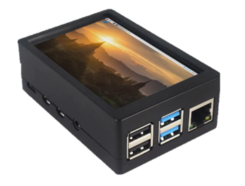
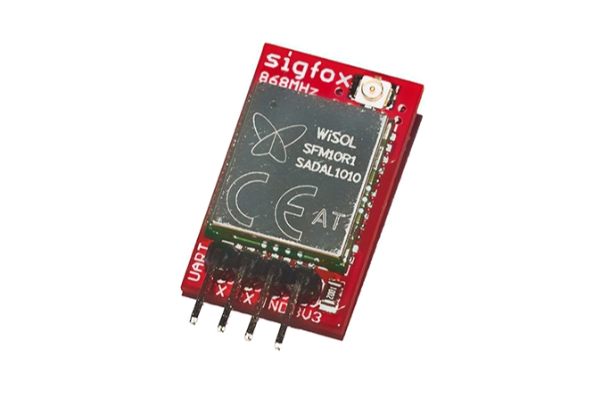
The first component of the system is the simulator of electric-vehicle, respectively, of its telematics unit (TCU), which is built on Raspberry Pi 4B. The microcomputer is housed in a box with a small touchscreen, inside which is also the Sigfox communication module connected to the UART interface, including a small antenna, and BMP280 temperature sensor, connected to the I2C bus.
The Raspberry Pi OS runs an application written in C++ and the Qt framework, using which the GUI for simulator control is created. Internally, the application consists of 4 components:
- GUI
- Simulator
- Broadcaster
- Logger
Simulator and Broadcaster components both run in their own QThreads, so they can be enabled/disabled independently from each other, for example for testing purposes, and do not interfere with each other. The exchange of data is realized through a mutual Vehicle object, to which all the components have a reference. For all read/write operations to Vehicle attributes, Qt’s QReadWriteLock mechanism is used, to avoid race conditions. The components run independently from each other, but if there is a condition when some action (redraw UI, broadcast, write a log immediately) is needed, Qt’s Signals and Slots mechanism is used to notify each other of these events (vehicle state was manually changed, charging has completed, etc.).
GUI consists of a few simple elements and is designed for small touch display - user can change actual charge level, charging current, vehicle state (off, idle, charging, driving), and see actual values and logs written to “console” (all the cout outputs are redirected there).
The application is executed using a systemd service upon system boot, and is launched in a fullscreen mode.
Simulation
The simulation process is made by mathematical logarithmic equations which imitate the process of real accumulator charging - from a rapid increase in lower charge levels, to a very slow increase close to full charge, also depending on the charging current. As the reference, the charging curve of the Tesla Model S with 85kWh battery was used, on a conventional “slow” charger with 50A DC current and on Tesla Supercharger stations, with 300A DC current. Equation parameters for currents between these values are calculated in a linear scale.
Broadcasting
The “broadcasting” to the cloud backend is possible in 2 ways:
- through WLAN - standard HTTP calls to backend API, over Raspberry’s network connectivity.
- through Sigfox technology - modern IoT, LPWAN network, of which network is available on wide areas worldwide.
The idea behind this is, that WLAN connectivity can be used when the vehicle is located at the brand’s own or partners charging stations, where the vehicle is able to automatically connect to a secure, local Wi-Fi network (be aware that Wi-Fi doesn’t have to be only 802.11b/g/n! (see wikipedia)). The other scenario is when the owner is charging his vehicle at home. For network requests, Qt Network module is used.
In other cases, when a local network is not available, Sigfox is used. In this case, the message is compressed into a 12B long packet (this is the maximum length for Sigfox payload) using bit-shifts and converting floats into half data type. Using this, we can fit 9 values into this 12 bytes long packet.
The content of the message is like this:
| Attribute: | Length: | Data type: | Unit: |
|---|---|---|---|
| • state | (3 bits) | enum | - |
| • current charge | (7 bits) | uint8 | perc |
| • target charge | (7 bits) | uint8 | perc |
| • current | (10 bits) | uint16 | amps |
| • elapsed time | (13 bits) | uint16 | minutes |
| • remaining time | (13 bits) | uint16 | minutes |
| • current range | (11 bits) | uint16 | km |
| • outside temperature | (16 bits) | half | minutes |
| • inside temperature | (16 bits) | half | minutes |
| 96 bits = 12 bytes | |||
These are not all parameters that the application simulates/vehicle’s TCU can provide. The rest of them (location coordinates, desired temperature set for AC, maximal charging current, fuel/electric consumption, etc.) can be sent as another packet with “extended” values, or can be sent only if WLAN connectivity is available. This part is not finished and the possible solution is opened.
After preparing the packet, it is sent to the serial port, where the communication module is connected. The module is controlled and configured using AT commands.
It’s needed to keep in mind, that Sigfox has a limitation in the number of messages that can be sent from one device in one day, so the broadcasting interval should be adjusted. In the case of WLAN connectivity available, the actual status can be reported to the cloud on a second basis. This configuration can be set in macros of components header files.
In the case of “broadcasting” via WLAN, the application can evaluate the success of the process; in the case of Sigfox broadcasting, there is no acknowledgment from the network possible. The availability of WLAN, Sigfox, and possibly also some other connectivity is evaluated before each transmission, so the simulator/TCU can always make the decision for using the best suitable channel, for each transmission. Both Sigfox and W-Fi broadcasting “modules” are made as individual classes, so it’s easy to replace them or add other communication technology, if it would be suitable.
See Communication Technologies article for more.


